Fike Test Data Proves Flap Valves are not Always Tested under Real-World Conditions
So much has changed at Fike during the past 75 years, but its core mission of protecting people and property around the world has always remained the same.
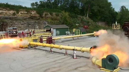
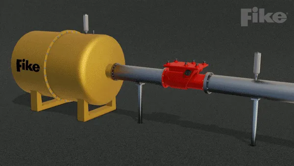
Fike’s Remote Testing Facility, located just a few miles from Fike Headquarters in Blue Springs, Missouri, is integral to this mission. Equipped with numerous testing vessels and decades of collective experience in explosion protection science, the Remote Testing Facility team often serves a watchdog role in the industry.
Recent test data gathered from this facility has empirically proven that potential performance problems exist with explosion isolation flap valves – many of which are ATEX-certified against the EN16447 standard – that are currently found in industrial processes and available for purchase around the world.
The purposes of this white paper and the supporting test data found within are to:
Highlight three problems of EN 16447 testing inconsistent with real-world processes that may provide misleading positive testing results
Inform owners of flap valves that these devices may fail to isolate deflagrations within the limits of their intended use
Recommend specific updates to the EN 16447 testing standard
Problem 1: “Protected Zone Pipelines” must be included in Flap Valve Testing
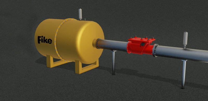
While nearly all flap valves in the field are installed between two pipelines, EN 16447 does not explicitly require the inclusion of a “protected zone pipeline” during the testing of flap valves.
Why it Matters
Without including the protected zone pipeline into certification testing, EN 16447-certified flap valves may not experience the same pressures and conditions during testing as they will when installed in an industrial or manufacturing process. Consequently, the pressures and oscillations generated in an actual installation will likely be significantly more severe than those generated during testing, leading to mechanical damage and isolation failure at deflagration conditions far below the certified ratings.
Problem 1: Evidence from Fike Test Data
Test 1.1 – Protected Zone Pipeline Not Included
EN Standards
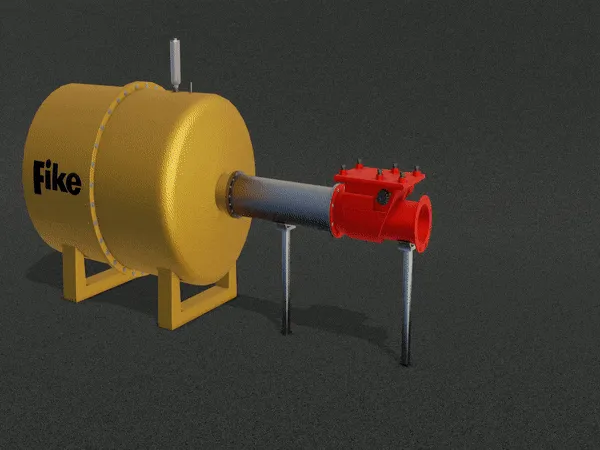
As allowed by EN 16447, this test did not include the pipeline on the protected zone of the process, but rather left the protected side of the valve exposed to atmosphere.
Test Data Findings:
- Minimal under-pressure (or re-opening pressure) occurs in unprotected zone.
- High-frequency but low-magnitude oscillations occur in the unprotected zone.
- The pressure loading on the flap is positive (holding the flap closed) for the vast majority of the test.
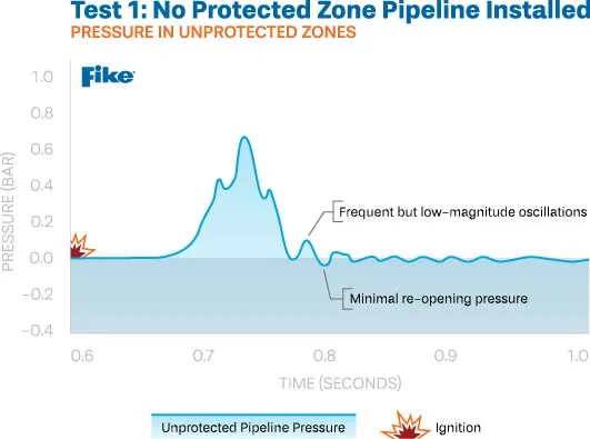
Without the inclusion of the protected zone pipeline, the data shows that the flap valve experiences non-concerning oscillations and pressure differentials, resulting in successful flame isolation.
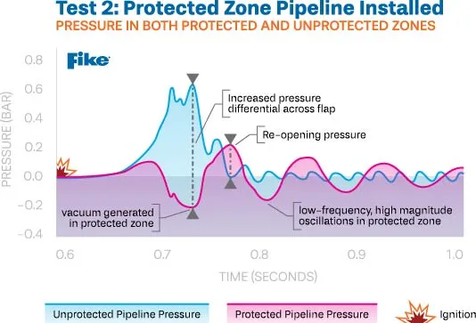
Test 1.2 – Protected Zone Pipeline Included
These tests included the pipeline in the “protected” zone of the process, which is representative of nearly all real-world installations. All other variables remained the same as previous tests that lacked the protected zone pipeline.
Test Data Findings:
- When the flap closes, a strong vacuum is created (0.2 bar) which “pulls” on the flap from the protected pipeline in addition to the pressure (0.6 bar) that is “pushed” against the flap from the unprotected pipeline.
- Both of these forces must be added together to represent the actual pressure differential experienced by the flap valve: 0.8 bar with the addition of protected zone pipeline versus 0.6 bar without.
- These figures vary greatly based on test conditions, fuel and other variables.
Of the 14 tests that included the protected zone pipeline, 13 of the tests observed the flap valve fail to isolate the flames due to flap/shaft deformation and locking mechanism failure. The forces that ultimately cause isolation failure are not accurately represented in testing without including the protected zone pipeline.
Furthermore, flames propagated through the flap valve after the pressure in the vessel had subsided, indicating a loss of flame-proof seal, even in cases where the flap valve closed properly and remained locked. When flame reached the protected zone, it aggressively re-accelerated further downstream since the combustion gases could not escape backward anymore due to the mostly closed valve.
Final Analysis of the Protected Pipeline Problem
The test data empirically proves the necessity of the protected zone pipeline to accurately simulate the conditions that a flap valve will experience during a deflagration in the intended application. Therefore, any testing that does not include the protected zone pipeline has likely resulted in the certification and installation of flap valves that may fail when exposed to real-world conditions.
Problem 2 – Tested Flap Valves must be Confirmed to have been Retained in the Fully Open Position
EN 16447 requires that the flap valve is held fully open until the appropriate time of release. However, the standard doesn’t provide explicit instructions to validate the timing of the release of the flap valve.
Why it Matters
In a real-world application, the process flow will keep a flap valve open until the pressure wave from a deflagration initiates its closure. Therefore, when testing flap valves without process flow, this timing must be precisely simulated. Premature flap closure leads to significantly reduced mechanical impact damage, lower pressure loading and decreased likelihood of flame exposure at the valve. By not monitoring the valve state throughout the test and using a precisely-timed release method, tests can falsely indicate a positive test result.
Problem 2: Evidence from Fike Test Data
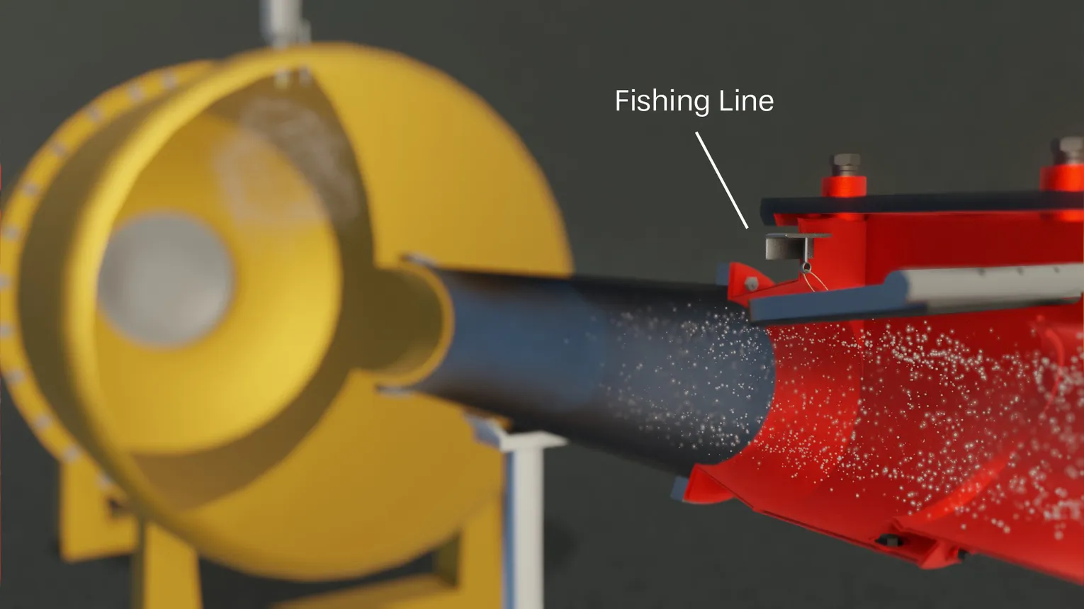
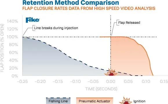
Test 2.1 – Flap Valve Held Open with Fishing Line
In this example, fishing line was used to retain the flap in the open position during injection. The fishing line is intended to break “after a time where the reversal of the flow into the test vessel is due to the developing explosion.” However, video recording and electronic flap angle measurement revealed the weak fishing line broke during dust injection and prior to ignition. Many flap valves were certified using this method.
Test Data Findings:
- The valve was approximately 85% closed at the time of ignition.
- Reduced closure velocities, low impact stress and minimal flap damage.
- Very low re-opening pressure in the protected zone pipeline.
- Flame never reached the valve and only propagated approximately 35% of the way to the valve prior to extinguishment.
- Flame isolation was successful, but under artificial conditions.
Using weak retention methods results in premature flap closing, which leads to a poor challenge to the valve and improper certification.
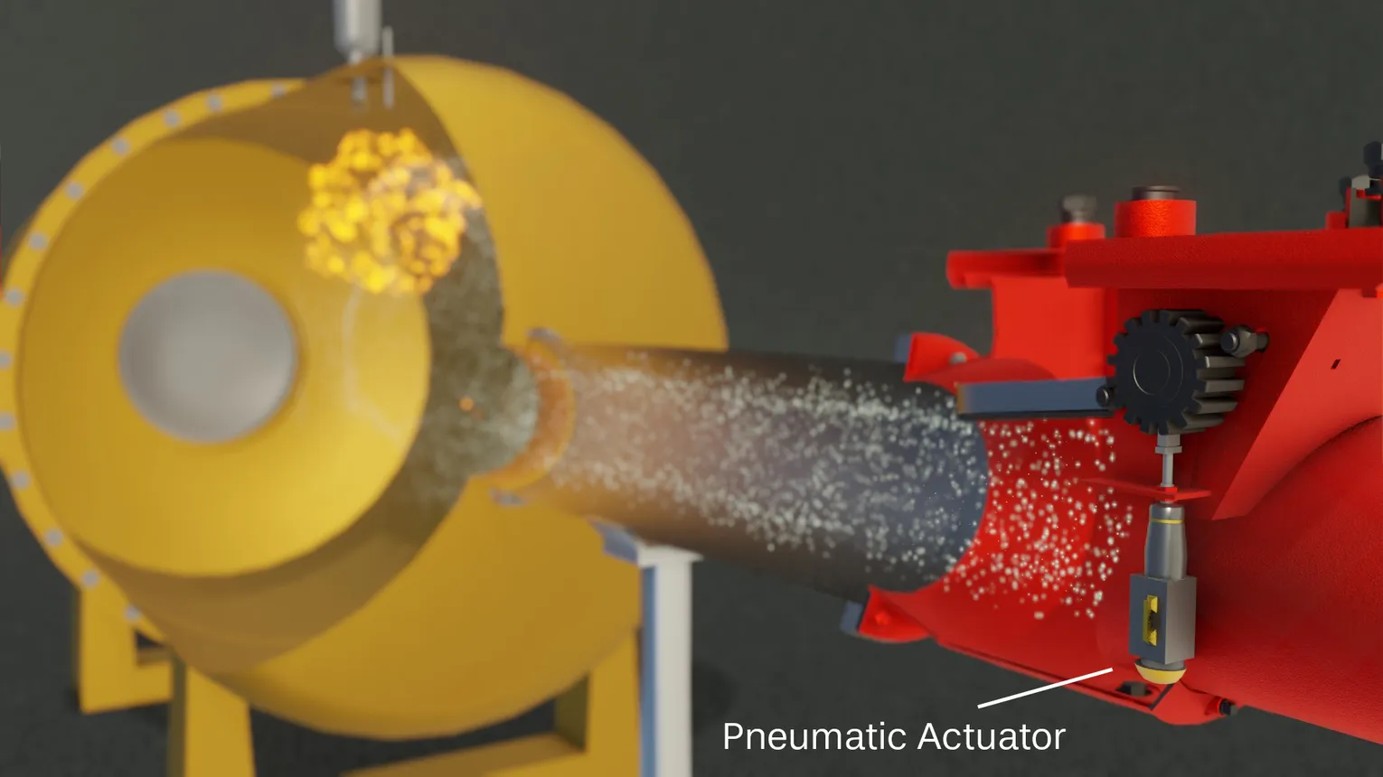
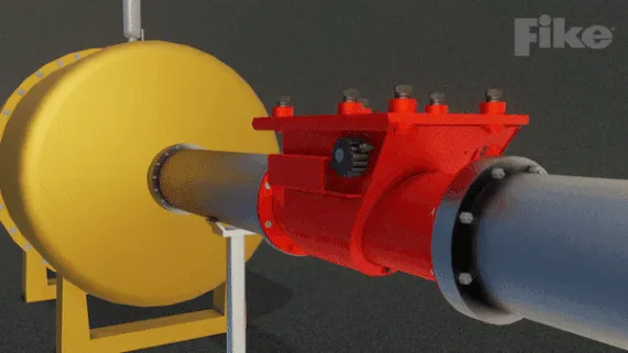
Test 2.2 – Flap Valve Held Open with Pneumatic Actuator
The flap was mechanically restrained with a pneumatic actuator, which was controlled to precisely release at the intended time.

Test Data Findings:
- Confirmed flap release exactly at the intended time.
- Significantly increased flap closure velocities, compared to weak retention testing method (>20 times the closure velocity)
- Significant damage to flap.
- Six times greater re-opening pressure in the protected zone pipeline than that observed in the weak fishing line retention method.
- Flame isolation failure due to valve damage.
The well-controlled pneumatic actuator retention method resulted in the flap valve accurately being released at the intended time, which reproduced the most representative conditions experienced by the flap valve in real-world situations. When the flap was properly released at the intended time, the flap valve failed to isolate the flames due to the increased closing velocities and subsequent mechanical seal failure.
Final Analysis of the Retention & Release Problem
While both tests were performed in accordance with the language found in EN 16447, they produced significantly varied results. Testing methods that allow the flap to close too early do not challenge the valve under the same pressure conditions it may endure in an installation. Additionally, pre-closure of the valve results in certification at reduced installation distances at which the valve may not work in a real-world application.
Fike recommends the standard be updated to explicitly require deterministic control timing and position monitoring, which would guarantee that the valve is in the fully open position until being released at the exact moment of ignition.
Problem 3 – Testing Vessels Must Include Explosion Vents/Bursting Foils, not Open Ports
During flap valve testing, EN 16447 does not explicitly require the inclusion of explosion vent panels or bursting foils on the vessel, which may lead to testing that instead includes ports open to atmosphere.
Why it Matters
Vessels in an industrial or manufacturing process almost always include an inlet, outlet and explosion vent panel. Rarely will a vessel include a port open to atmosphere. Therefore, flap valve testing that includes an open port in place of an explosion vent panel or bursting foil greatly affects the pressure experienced by the flap valve.
Problem 3: Evidence from Fike Test Data
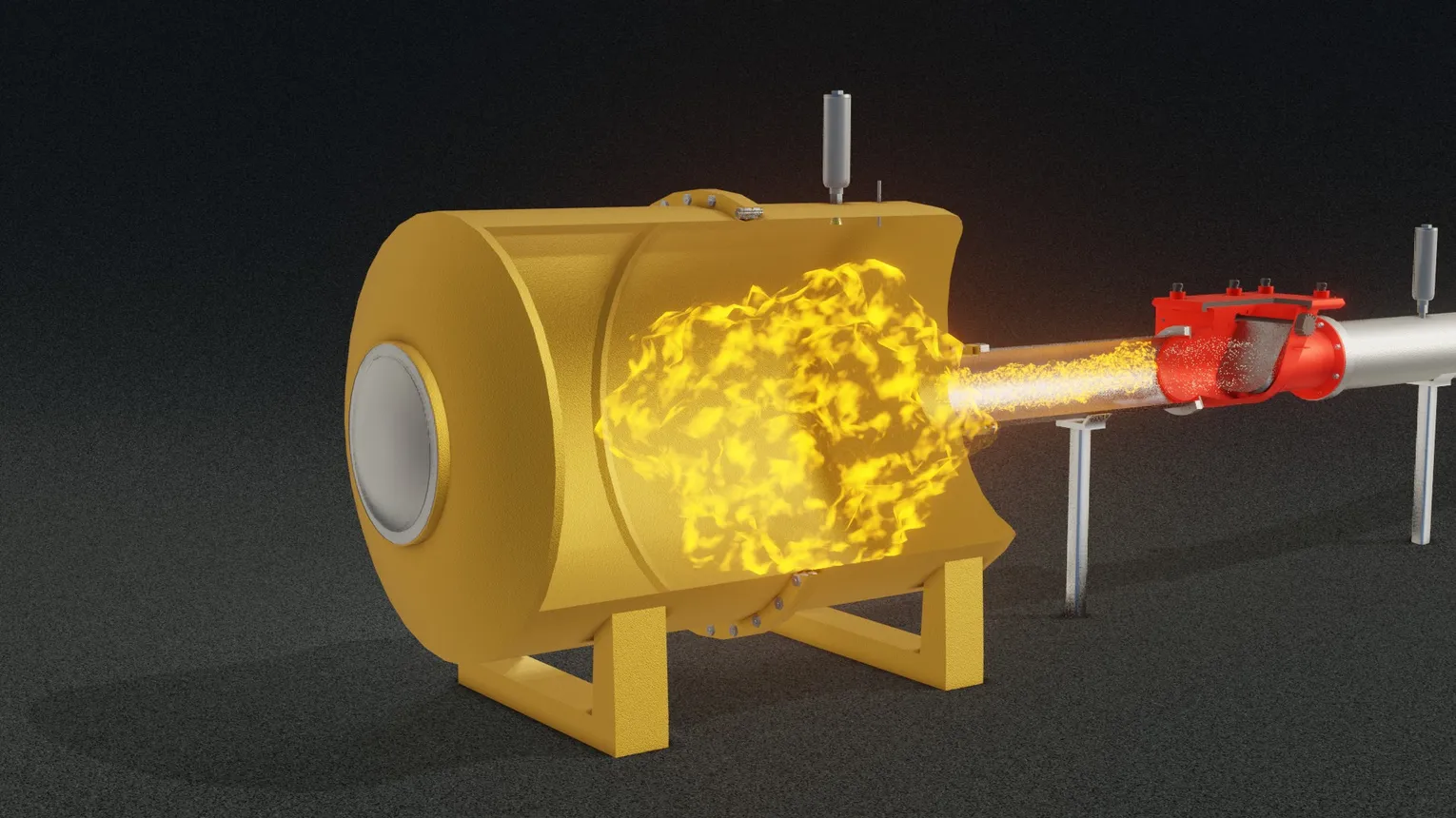
3.1 Tests with Open Ports
Test Data Findings:
- Just after ignition, flame propagates toward both the open port and the valve. The rise of pressure toward the flap valve is reduced due to the immediate venting through the open port.
- As the valve begins to close relatively slowly (because of the slow rise of pressure), the deflagration shifts toward the open port and away from the valve. Flame approaches the valve very slowly.
- The deflagration pressures in the vessel subside prior to flame arriving at the valve.
- Due to fuel dropout in the pipeline, flame may never make it to the valve.
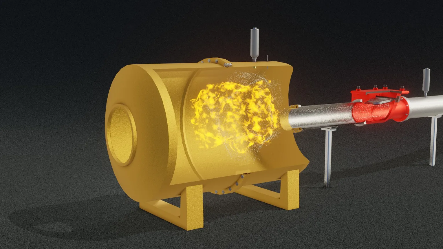
3.2 Tests with Explosion Vents
Test Data Findings:
- Just after ignition, and as long as the explosion vent panel/bursting foil is closed, flame propagates preferentially toward valve.
- Flame approaches the valve at a high speed, forcing the flap valve to close firmly.
- Flame arrives at valve just after closure and the explosion vent panel ruptures.
- Flame is present at the valve seal while the system is under pressure, adequately challenging the flame seal.
Problem 3: Evidence from Fike Test Data
If an open port is included in the test vessel (which will rarely be the case in an actual application), the deflagration escapes out of the port, the rate of pressure rise is significantly lower, and flames do not travel down the pipe and challenge the valve appropriately. Therefore, the flap valve will not experience the same conditions that it will in an actual installation.
Excluding an explosion vent panel/bursting foil from testing may ultimately result in the flap valve being certified at higher pressures and/or closer placement to the vessel than it can successfully perform in actual installations.
Fike’s Official Position on Flap Valve Safety
Preventable loss of life in the industrial workplace is a never-ending problem that Fike strives to eradicate with its comprehensive engineering, manufacturing and, in this case, testing capabilitie

Fike’s Remote Testing Facility team observed severe issues and inconsistencies in EN 16447 flap valve certification testing and consistent isolation failures when flap valves are exposed to real-world explosion conditions. Fike feels an ethical obligation to raise these concerns to flap valve owners and to the greater explosion protection scientific community.
Therefore, in the interest of safety, flap valve owners should question whether the testing of these devices included…
- A protected zone pipeline?
- Confirmation that the flap valve was released precisely at the time of ignition?
- An explosion venting panel or bursting foil on the test vessel, rather than an open port?
If the answer is “no” to any of these questions, the flap valve did not experience during testing the same real-world conditions it could experience during a deflagration and may consequently fail to protect the facility.
When plant owners, health and safety managers and original equipment manufacturers purchase explosion protection devices such as flap valves, they also purchase a certain degree of trust.
Trust in the device’s engineering. Trust in the device’s manufacturing. And, in this case, trust in the testing and certification that, in the event of a potentially catastrophic event, the device will perform precisely as intended.
These users have no reason to believe otherwise.
In May 2020, Fike presented these findings to the EN standards committee and is currently working to update the testing standards, which will ultimately improve the collective understanding of the forces these flap valves can actually endure during an explosive event.
It is Fike’s official position that the EN 16447 standard should be updated, and flap valves tested with the aforementioned problems should either be retested, derated or replaced with another explosion isolation device.